Abstract
A reference measurement is required when measuring the power
loss of installed fiber cable using an optical source and
power meter. Different methods can be used when making a reference
measurement. There is occasional confusion over which method
should be used under which circumstance. The reference measurement
to use depends upon the configuration of the cable plant under
test. There are three basic cable plant configurations and three
corresponding reference methods.
The most common horizontal backbone configuration features
a cross-connect panel or outlet at each end of the cable plant.
This is the TIA-568-B and ISO 11801 specified topology. The
One Jumper Reference Method is recommended for this familiar
network
design.
Less common are networks where the active devices are directly
connected to one another or where a single cross connect panel
is utilized. The reference methods for these networks use
three and two jumpers respectively. The three reference measurement
methods are defined in TIA/EIA-526-14A and summarized herein
along with a discussion of why and how loss is measured.
Why measure loss?
You measure loss to determine whether the optical power loss
of the installed cable plant is within specification, thus guaranteeing
proper network performance prior to connection of the active
components.
An optical fiber communication system is comprised of a transmitter
(Tx) and receiver (Rx) physically connected by a passive fiber
optic cable network. This network, commonly referred to as the
"cable plant",includes fiber cable and may include
other passive optical components. The strength of the transmitted
optical signal diminishes as the signal travels through the
cable plant. Excessive signal loss through the cable plant prevents
the receiver from accurately interpreting the received signal.
What is loss?
Loss is the difference between the optical power launched
into a fiber cable plant (PIN) and the optical power received
at the far end (POUT). It can also be expressed logarithmically
as the ratio of received optical power (POUT) to launched
optical power (PIN).
Loss (dB) = PIN - POUT where P in same logarithmic units (dBm)
Loss (dB) = -10 log10(POUT/PIN) where P in same units (mW)
How do you measure loss with a source and
meter?
You can very accurately measure loss with an optical source
and a power meter. The source represents thetransmitter while
the power meter represents the receiver.
Step 1, measure PIN: To measure PIN, the source is connected
to the power meter via a jumper cord.Multiple cords and adapters
may be used. The PIN power is read off the meter. This step
is commonly
called taking a "reference" measurement.
Step 2, measure POUT: To measure POUT, the same source and
power meter are connected to the ends of thecable plant under
test. The POUT power is read off the meter.
Step 3, calculate loss: The optical loss is the difference
between PIN and POUT. Many commerciallyavailable power meters
can store the reference measurement and display loss directly.
Which reference method should be used?
Test jumpers and adapters are needed to connect the optical
source and meter to the cable plant under test.The loss of
a 1 to 5 meter test jumper is negligible but the loss at the
connection point between test jumper and cable plant can be
significant. Since the objective is to measure the loss in
the cable plant only, any additional losses from test cable
connections must be subtracted from the measured end-to-end
loss. This can be accomplished by properly configuring the
reference measurement.
There are three reference methods. Which method to use depends
upon the configuration of the cable plant under test. In addition
to fiber cable, the cable plant may contain panels, jumpers,
adapters, splices, and other passive elements, but may not
include active components. There are three common plant configurations:
1. Direct termination: The Tx is directly terminated to the
Rx.
2. Patch panel: The Tx is terminated to the Rx through an
intermediate patch panel.
3. Dual patch panels: Patch panels are located at each end
of the cable plant.
If the cable plant is of the direct termination variety, three
jumpers and two adapters are used in the reference set-up.
If a single patch panel is present, two jumpers and one adapter
are used. If the cable plant
utilizes two panels, then only a single jumper is used in
the reference measurement. These three reference methods are
described in greater detail.
Direct Termination Cable Plant = 3 Jumper/2
Adapter Reference Method (TIA Method C):
The transmitter is directly terminated to the receiver as
illustrated in the top figure. In this configuration,three
jumpers and two adapters are necessary when making a reference
measurement as illustrated in the middle figure. The center
jumper is removed and the test jumpers are mated to the cable
plant using the two adapters as illustrated in the bottom
figure. This method result includes only the losses contained
within the cable plant.
One Patch Panel Cable Plant = 2 Jumper/1
Adapter Reference Method (TIA Method A):
The transmitter and receiver are joined at an intermediate
patch panel as illustrated in the top figure. The panel can
be on either the Tx or Rx side of the cable plant. The patch
panel includes an adapter. In this configuration, two jumpers
and one adapter are necessary when making a reference measurement
as illustrated in the middle figure. The jumpers are then
de-coupled from the adapter and mated to the cable plant using
the adapter and the existing patch panel as illustrated in
the bottom figure. This method result includes one connection
loss in addition to the losses contained within the cable
plant.
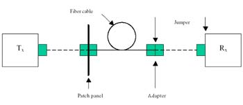
Dual Patch Panel Cable Plant = 1 Jumper
Reference Method (TIA Method B):
The transmitter and receiver are mated to patch panels at
each end of the link. The cable plant is between the panels
as illustrated in the top figure. The patch panels include
adapters. In this configuration, one jumper is necessary when
making a reference measurement as illustrated in the middle
figure. The jumper is removed from the meter and mated to
the first patch panel. A second jumper is added between the
second patch panel and meter as illustrated in the bottom
figure. This method result includes two connection losses
in addition to the losses contained within the cable plant.1
Summary:
The choice of reference method is dependent upon the configuration
of the cable plant under test. The proper reference set-up
will insure that only the loss in the cable plant is measured
and not additional losses from test jumpers and adapters.
There are three basic cable plant configurations and three
corresponding reference methods. These three reference methods
are described in greater detail in TIA/EIA-526-14A, "Optical
Power Loss Measurements of Installed Multimode Fiber Cable
Plant." TIA Method A is consistent with FOTP-171 method
B. TIA Method B is consistent with ANSI/TIA/EIA-568-B. Since
the most common network design is the TIA-568-B/ISO 11801
topology featuring a cross-connect panel or outlet at each
end of the cable plant, the One Jumper Reference Method is
most commonly applied. Once you understand how to choose an
appropriate reference method and use it consistently, you
can be assured of accurate, repeatable results when measuring
the loss of fiber optic links.
The loss of the second jumper is included in the cable plant
measurement but as the jumper loss is negligible, measurement
accuracy is acceptable.
|